How to put liners on a vase. How to replace the crankshaft bearings without removing the engine? Some Tips
You will need
- - a set of wrenches for engine disassembly;
- - caliper;
- - calibration plastic wire.
Instruction
First you need to dismantle the engine and install it in a position convenient for further disassembly. Next, you need to remove the sump, oil pump and unscrew the main, connecting rod caps that cover the liners, which in fact are plain bearings. In this process, the participation of a specialist is desirable, who, using a caliper, will determine which neck crankshaft became the "culprit" of improper engine operation.
The next step is to bore the crankshaft to the nearest size. It is necessary to purchase liners only after the grinding of the necks has already been done - the mechanic-minder will tell you the required size of the liners. Bearings are sold in a set designed for connecting rod or main journals.
The liners are installed on a new or polished crankshaft. For engines manufactured at VAZ, there are 4 repair sizes of liners in 0.25 mm increments: 0.25 mm, 0.5 mm, 0.75 mm, 1.0 mm. For engines manufactured at GAZ and AZLK (plus the Izhevsk plant), there is also a 5th, 6th crankshaft bore size: 1.25 mm and 1.5 mm; the size of the liner is indicated on its surface.
The bored crankshaft must be blown with compressed air to remove chips remaining after machining the part. When installing the liners, the latter must be lubricated engine oil. Elements of the crank mechanism are mounted "lock to lock". If you do not have experience repairing an engine, then it is better to entrust the work to a specialist.
note
When boring the crankshaft, the sequence will not necessarily be observed: with a lot of wear on the crankshaft journals, it is possible to grind them through the size. Bearings are sold in a set designed for connecting rod or main journals. The crankshaft is one of the most expensive engine parts; therefore, timely boring and grinding of the necks significantly extends the life of the motor as a whole.
Useful advice
The determination of the need to replace the liners is carried out using a special calibrated plastic wire, which is installed on the main or connecting rod journal of the crankshaft. Next, a cover with an insert is placed and tightened with a force of approximately 51 N / m (you will need a torque wrench). The gap can be determined by the level of flattening of the wire.
Sources:
- Crankshaft balancing
Key parameter of any engine internal combustion is its working volume, measured in liters. The specified value has a direct impact on the power developed by the motor. And the more powerful engine, the more dynamic the car and the higher the comfort of driving it.
You will need
- - machine for boring cylinder blocks,
- - new piston group.
Instruction
Boring new engine does not make any sense, except for those cars that are preparing to participate in sports competitions. In all other cases, the cylinder block is bored during the overhaul of the power unit.
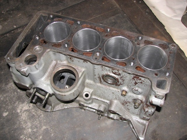
Due to the fact that the cylinder block is bored on special industrial equipment, in the course of preliminary preparation for this process, engine dismantled from the engine compartment of the car.
After this condition is met, the motor is completely disassembled, and then troubleshooting is performed for all the parts from which it was recently assembled.
The “bare” engine block is delivered by auxiliary transport to the workshop to a specialist in boring these parts. The master, after examining and performing the necessary measurements of the internal surfaces of the cylinders of your block, will issue recommendations on the purchase of a repair piston group of a certain size, which, after purchase, is delivered to him, to the workshop.
After boring the cylinder block, the engine is assembled, after which the overhaul of the engine is considered completed, and as a result of the repair power unit endowed with an increased displacement and acquires increased power.
Related videos
Crankshaft balancing is performed on a special dynamic stand, which allows you to determine with great accuracy the location and mass of imbalance compensators. Compensation is performed by removing or welding metal.
Proper balancing of an automobile crankshaft not only increases the duration of its life cycle, but also reduces power losses, reduces noise in the cabin and helps to reduce wear on body and transmission components. Both crankshafts in operation and new crankshafts with assembly and manufacturing defects are subjected to balancing.
Balancing conditions
To eliminate the imbalance of the crankshaft, it is necessary to check it on a dynamic stand. This equipment is included in the equipment of all major stations Maintenance and allows balancing crankshafts of various designs.
The crankshaft must be balanced together with the flywheel, as they work on the engine as part of a single rotor. The shaft is attached to the trunnions of the balancing machine, which have collets or three-jaw chucks to secure the balanced unit.
Balancing order
The crankshaft with the flywheel fixed in the machine is set in rotation, the frequency of which corresponds to the working speed. The imbalance is detected using a laser sensor that can move along the length of the crankshaft.
The balancing characteristic is recorded and processed using a specialized software installed on the computer, which is part of the equipment of the balancing stand.
Based on the results of determining the imbalance, performed on a dynamic balancing stand, the installation locations of balancing weights or metal removal points are determined. The mass of compensators is also indicated.
In a garage workshop, the crankshaft and flywheel assembly can be statically balanced. To do this, you need to install the crankshaft on 2 prisms, after which, using the selection method, add a balancing weight until the rotor stops turning under its own weight. Plasticine can be used as a temporary load during testing.
Both static and dynamic balancing of the crankshaft require the subsequent elimination of the imbalance. These measures can be carried out in two ways - by welding additional metal or drilling holes in certain places. To remove metal, special balancing belts are provided in the crankshaft design, so the presence of holes does not weaken the part below an acceptable level.
Related videos
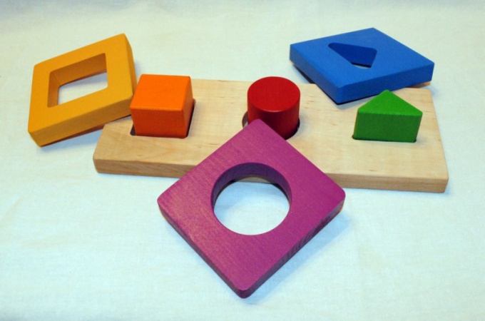
What to do with the baby? This question comes up fairly regularly. Even favorite toys get boring sometimes. With liners, a small child can fiddle for quite a long time, moreover, such an activity brings considerable benefits. The kid learns to compare objects in shape and size, while developing fine motor skills. You can also make inserts yourself.
You will need
- - PVC tiles of different colors or plywood;
- - a sharp knife;
- - awl;
- - jigsaw;
- - oil paints;
- - varnish;
- - sandpaper;
- - drawing accessories;
- - pictures depicting figures of animals, birds, fish, flowers.
Instruction
The insert is a plate with slots into which the figures are inserted. Start with the most basic geometric shapes. It is best to make such a game from the most ordinary PVC tiles, it is quite easy to cut with an ordinary sharp clerical knife. There are also special knives for linoleum, you can buy one at any hardware store. Choose tiles in two colors. In one you will make cuts. The other will serve as material for the figurines.
Use a compass to draw circles on the second tile. They should be different size. To make it easier to cut them out, make holes in several places with an awl or drill. Cut out the circles. Try to keep them even. Gently sand the edges so that there are no nicks. Of course, while playing with toys made of such material, the child does not risk planting a splinter. But any game should look beautiful.
Lay the circles on the tile intended for the field. Circle them. This is easiest done with a ballpoint pen. Make a slit for each circle, and then sand the cuts. In exactly the same way, inserts with squares and other geometric shapes can be made. Instead of tiles, you can use plywood, but then you will need a jigsaw. All details of the plywood game are best painted in bright colors or varnished.
Figures can be anything. For example, pick up pictures with silhouettes of animals. It is desirable that they be about the same size. They can be found on the Internet, scaled in any graphics editor, printed and transferred to tiles or plywood. Try to choose figures with a minimum amount of small details, it will be easier to cut them out.
Related videos
Useful advice
The material for such games can be used very different. For example, penofol and other soft foams. Hard cardboard is also suitable, but the game will need to be coated first with water-based paint, then with gouache and varnish.
Insert is issued if all sections on work or awards are completely filled in the work book. The insert form is unified and approved by the Government of the Russian Federation under No. 225. The direct execution of this document is carried out in accordance with the rules for maintaining work books, paragraph No. 38.

You will need
- - liner
- - employee's passport
- -document of education or advanced training
Instruction
When making an insert on the title page of the work book, you should put a seal and indicate that the employee has been issued an insert, put down its series and number. Each new insert must be issued with a separate seal. Insert valid only with a work book, which is stamped and contains information about its issuance.
Before filling out the insert in the labor book, it is necessary to receive documents from the employee on the basis of which the insert will be filled out. You cannot fill it out according to the information indicated on the title page of the work book, since personal data could change. The employee must submit a passport, diploma or document on advanced training. Based on the submitted documents, the title page is filled in at the insert.
Insert should be sewn under the cover of the work book. One employee can be issued as many inserts as required for his labor activity. About all inserts that are issued, information should be put on the title page of the work book in the form of a seal and an indication of the number and series of the issued inserts.
Insert into labor book is not an independent document when applying for a job. It should be presented directly with the work book, on the title page of which information about the issuance of the insert is indicated.
Correction of incorrect entries made in the insert must be made in accordance with the rules that indicate the correction of incorrect entries in the work book. Under the incorrect entry, it is necessary to indicate that it is incorrect, put the seal of the organization and the signature of an authorized person. Make a correct entry under the next serial number.
note
Rules for registration and filling. How to fill out a work book? All entries in the workbook are made without abbreviations and have their own serial number within the corresponding section. 2 columns - the date of entry in Arabic numerals (it must correspond to the date of admission, transfer, dismissal and the date of preparation of the relevant document (order, order, etc.), and not the day when you fill out the work book).
Useful advice
How to issue a work book. The form of the work book and the rules for its maintenance (hereinafter referred to as the rules) were approved by Decree of the Government of the Russian Federation of April 16, 2003 No. 225 “On work books”. And the instructions for filling out work books are contained in the Decree of the Ministry of Labor of Russia dated 10.10.2003 No. 69 (hereinafter referred to as the instruction). If all pages of one of the sections are filled in the work book, an insert is sewn into it. It must be drawn up and maintained in the same order as the work book.
To confirm that the child is a Russian citizen, the parents had to obtain insert about citizenship. Without this document, travel abroad was not allowed, and the children did not fit into the passport to their parents.

You will need
- - Copies of parents' passports;
- - a copy of the child's birth certificate;
- - extract from the house book.
Instruction
In accordance with Decree of the President of the Russian Federation No. 1325 of November 14, 2002, every child under the age of 14 was supposed to be given insert citizenship in addition to the birth certificate. Identification insert child as a citizen of Russia, which allowed parents to freely take the baby abroad. The insert was issued upon a written request from the parents. Also, in order to obtain this document, it was necessary to submit the following documents to the regional migration service authorities: an extract from the house book, a birth certificate child and a copy of it, copies of parents' passports. The insert was issued literally within 2-3 days.

However, the need to have such insert on the child Not all parents knew. And often there were situations when a trip abroad was disrupted due to the fact that child not issued insert about citizenship. Therefore, in February 2007, a corresponding Decree of the Government of the Russian Federation was adopted to cancel the issuance of insert her and replacing them with a citizenship stamp. This seal is put in the same place, in the migration service, on reverse side birth certificates.
According to the Order of the Federal Migration Service of the Russian Federation No. 68 dated March 19, 2008, parents child, who was born in the Russian Federation and is a citizen of Russia in fact, migration service employees are required to certify this fact at the first request. Employees of the FMS of Russia certify precisely by affixing such a stamp. Get a citizenship stamp child either at the place of residence of the parents, or at the place of birth child, or at the place of actual
Crankshaft liners and connecting rods are the most important parts of any engine, despite their small size. This article, more aimed at beginners, will go into detail about these parts, their installation, gaps, knocks, when to change them, and much more.
In general, the durability of plain bearings, called liners, both main and connecting rod, depends very much on the condition and clearances between the liners and the parts mating with them, namely the main and connecting rod journals of the crankshaft. We will talk about the correct (permissible) working clearances of the liners and crankshaft journals a little later, but first we will consider what parts such as main and connecting rod liners are and what role they play.
It's no secret that an internal combustion engine works by burning fuel in the combustion chambers and expanding the gases that appear during the combustion process, which push the engine under high pressure, and they, in turn, push with great force.
Well, the connecting rods with their lower holes (lower heads) abut and push with great force the neck of the crankshaft, which has the shape of a crank and the crankshaft at the same time converts the reciprocating movement of the pistons and connecting rods into a rotational movement of the flywheel, which transmits rotation to the driving wheels of the car through the transmission (motorcycle, etc.). It is easy to guess that in this case, huge loads and friction arise between the holes in the lower heads of the connecting rods and the crankshaft journals.
And it is the main and connecting rod bearings, which are the plain bearings of the connecting rods and necks, that are installed between the holes in the connecting rod heads and the crankshaft journals, and they are required to reduce friction and withstand huge loads between the connecting rod and the crankshaft journal.
To reduce friction, (except for supplying engine oil under pressure using ) liners modern engines have an anti-friction coating and are also made of ductile alloys (usually aluminum) in order to withstand heavy loads and not collapse.
In addition, the plastic and anti-friction material of the liners does not allow the crankshaft journals to wear out quickly. The liners gradually wear out themselves, do not allow the crankshaft journals to wear out quickly, because the liners are softer than the surfaces of the necks themselves. Of course, when the engine is running on the surfaces of the crankshaft journals, the oil film created by the lubrication system does not allow the formation of scuffs, sticking (or even collapse), but the quality material of the liners itself is also of great importance.
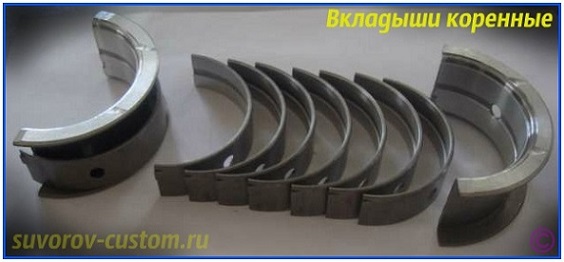
Liners are indigenous and connecting rod.
Indigenous liners —
the place of their installation in the engine block in special places (beds), and the places of their installation and friction with the crankshaft main journals on four-cylinder engines are in five places (supports) in the lower part of the engine block.
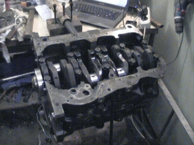
The main bearings of the crankshaft usually have grooves and holes for better lubrication (see photo) and in fact they are supports for the crankshaft when it is laid in the engine block and, of course, they are supports and bearings of the crankshaft when the crankshaft rotates in the engine block.
And of course, the main bearings are plain bearings for the main journals of the crankshaft. In general, the entire crankshaft of the engine rests and rotates on the main bearings, and from this the importance of these parts and their technical condition is quite clear.
Connecting rod bearings their location is clear from the name and of course they are installed in the lower heads of the connecting rods, and the connecting rods, in turn, are mounted through the connecting rod bearings on the connecting rod journals of the crankshaft.
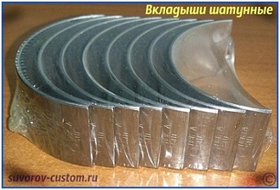 Connecting rod bearings, as a rule, have a simpler device and are supports and plain bearings for the lower heads of the connecting rods and the connecting rod journals of the crankshaft. Through the connecting rod bearings, large loads are transferred from the connecting rods (their lower heads) to the connecting rod journals of the crankshaft. And of course the importance of these details is quite clear.
Of course, after a certain engine run, even with the highest quality and serviceable lubrication system, both the main and connecting rod bearings gradually wear out and should be changed (more on replacement later). As a rule, the driver is notified of the wear of the liners by knocks and loss.
Knocks of connecting rod and main worn liners differ in sound and an experienced driver or mechanic can easily determine which of the liners is knocking.
Knock of main liners usually metallic, dull tone. Easily detected when the motor is running on idling with a sharp gas supply (a sharp increase in crankshaft speed). And the frequency of knocking increases with increasing crankshaft speed.
Knock of connecting rod bearings sharper than the knock of the main ones and it is just as well audible at idle engine speed with a sharp gas supply and a sharp increase in crankshaft speed. And the liners of which connecting rod are worn out and knock, it is easy to determine by turning off one by one or (if the knock disappears when a cylinder is turned off, then it is in this cylinder that the connecting rod liners are worn).
As for the drop in oil pressure, this occurs not only from the wear of the liners, but also for other reasons, for example, from, or from, well, or from mating wear.
Therefore, before changing the liners, you should first make sure of the exact cause of the pressure drop, it is possible that the main and connecting rod liners are not the cause of the oil pressure drop (especially if they work without noise and knocks).
Replacing the crankshaft liners with repair ones.
As mentioned above, with an increase in the total engine mileage, the liners gradually wear out, the gaps between them and the crankshaft journals increase, noise (knocking) appears, the oil pressure drops and the worn liners need to be replaced with new ones. In addition to the liners, the crankshaft journals also gradually wear out, while grinding the crankshaft is required and already required repair liners, which are 0.25 mm thicker.
I have already written about all this (as well as about measuring and selecting repair liners, grinding necks and other nuances) in the article “Grinding the crankshaft”. But even in this article, the main important points regarding the crankshaft liners, both main and connecting rod, should be described.
To begin with, it should be said that repair liners for most cars and motorcycles are produced with an increased thickness of 0.25 mm (0.25; 0.5; 0.75; and 1 mm) and this allows four repairs to be made for most engines. However, in some cases, for example, when, after careless operation of the engine, sticking, scuffing, deep scratches on the crankshaft journals, after eliminating these defects by grinding the journals, sometimes you have to jump over the repair size.
That is, after a deeper grinding of the crankshaft journals (in order to get rid of defects on the necks), it is necessary to install repair liners that are not 0.25 mm thicker, but already 0.5 mm thicker.
Or it happens the other way around, that with a small mileage of the engine and preventive maintenance of the engine (for example, replacement), someone decides to replace both the liners, and in the normal state of the crankshaft journals, the liners are replaced not with repair ones, but only with new ones of a standard size.
All these nuances and what size the crankshaft liners should be installed should be determined by measuring the crankshaft journals and measuring the working clearance between the liners and the crankshaft journals. In general, the working clearance (which has certain allowable values that should be followed) is the main starting point when deciding what to do with the engine (more precisely, with the crankshaft and liners) during repairs.
Therefore, after disassembling the engine, the first step is to inspect the crankshaft journals and measure them, as well as measure the working clearance between the liners and the crankshaft journals. But first, when examining the necks, we make sure that there are no scratches, marks, traces of sticking on them.
Next, use a micrometer to measure the diameter of the necks in two diametrically opposite planes in order to identify the ovality of the neck, and if there is an ovality that exceeds the tolerance, then it is necessary to eliminate it by grinding the necks (I will write about the tolerances for the ovality of the necks a little lower).
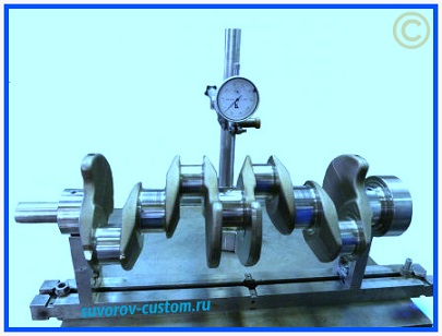
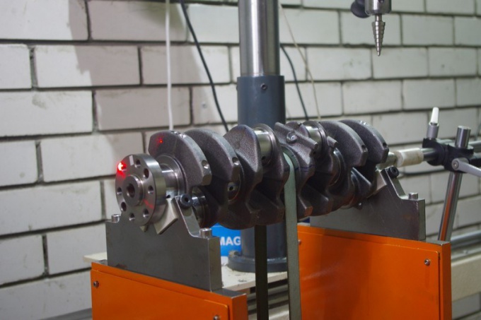
The ovality of the crankshaft main journals can be easily identified not only with a micrometer, but also with the help of, while laying the crankshaft on two prisms (see photo) and scrolling it by hand.
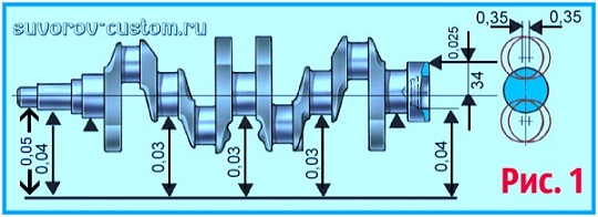
In general, two prisms and a dial indicator allow you to fully check the crankshaft for runout, the tolerances of which are shown in the figure on the left and which should not exceed:
- main journals and the landing surface of the crankshaft under the drive gear oil pump- no more than 0.03 mm.
- landing surface on the crankshaft for the flywheel - no more than 0.4 mm.
- landing surface of the crankshaft under the pulleys and friction surfaces of the edges - no more than 0.05 mm.
All the tolerances described above are shown in Figure 1.
 Also (as mentioned above), it is necessary to measure the diameters of the crankshaft journals, both main and connecting rod, using a micrometer. And if during measurements it turns out that the wear of the necks is more than 0.03 mm (look for the standard size of new necks in the manual of your engine), and also if there are scuffs, risks, scratches on the necks, then the necks should definitely be ground to the nearest repair size.
We also measure the necks with a micrometer in diametrically opposite places, and if during measurements it turns out that the ovality of the necks exceeds the tolerance of 0.03 mm, then it is necessary to get rid of the ovality of the necks by grinding them to the nearest repair size.
The ovality and taper of the connecting rod and main journals of the crankshaft after grinding should not exceed 0.005 mm. And the displacement of the axes of the connecting rod journals from the plane passing through the axes of the connecting rod and main journals after grinding should be within ± 0.35 mm. - keep this in mind when picking up your crankshaft from the grinder.
To check the tolerances described above for competent grinding, we again install the crankshaft with extreme main journals on two prisms and set the crankshaft so that the axis of the connecting rod journal of the first cylinder is in a horizontal plane passing through the axes of the main journals. After that, with a dial indicator, we check the displacement in the vertical direction of the connecting rod journals of the second, third and fourth cylinders relative to the connecting rod journal of the first cylinder of the engine.
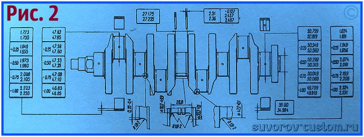
The main dimensions for the repair grinding of the crankshaft VAZ 2108-09
After grinding the crankshaft journals to the nearest repair size, you can install new crankshaft repair liners. For most engines, steel-aluminum thin-walled liners are made. And as a rule, the upper liners (for domestic front-wheel drive VAZ cars) of the first, second, fourth and fifth bearings have a groove on the inner surface, and the lower liners do not have grooves. And the upper and lower liners of the third support do not have a groove. Well, all connecting rod bearings (both upper and lower) do not have grooves.
It should be remembered that no adjustment work can be done on the crankshaft liners. And if your used liners have scuffs, risks, or delamination of the anti-friction layer, then of course such liners should be replaced with new ones.
The working clearance between the liners and the crankshaft journals can be checked by calculation after measuring the parts with a micrometer. But it is much easier to check the gap with a specially designed plastic calibrated wire (like a fishing line).
Having bought the wire and removed the covers of the plain bearings, before checking, we thoroughly clean the working surfaces of the liners and crankshaft journals and lay a piece of wire between the checked neck and the liner. Next, we install a connecting rod with a cap or a cap of the main plain bearing (depending on which neck clearance you are checking) and then it remains to tighten the nuts or bolts of the bearing caps.
The connecting rod bolt nuts should be tightened to 51 N m (5.2 kgf m). Well, the bolts of the main bearing caps should be tightened with a torque of 80.4 N m (8.2 kgf m). This is the data of the required tightening torque for VAZ front-wheel drive cars, and for engines of foreign cars and other cars, you should check the data in the manual of a particular (your) engine.
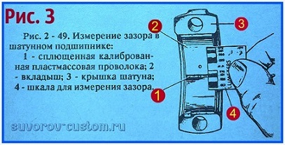 After tightening to the moment described above, the cover is removed again, the flattened wire is removed and using a special scale shown in photo 3 on the left (the scale is included with the wire), the working gap between the liner and the crankshaft journal is checked.
For most engines with a volume of not more than 1.5 liters, the nominal design working clearance should be in the range of 0.02 - 0.07 mm for the connecting rod journals, and 0.026 - 0.073 mm for the crankshaft main journals. However, I advise you to clarify these data in the manual of a particular (your) engine.
If the gap is less than the maximum allowable 0.1 mm for connecting rod and 0.15 mm for main journals, then these liners can be used again. If the working gap measured with a wire is greater than the maximum allowable, then the liners on these necks can be installed with standard new ones. However, if the gap is more than the maximum allowable, then I advise you to measure the wear of the neck, it may be time to grind them. In general, any neck should first be checked for wear and ovality.
If the crankshaft journals are worn out (the tolerances were described above), then they should be ground to the nearest repair size and new repair bearings of increased thickness are installed accordingly.
Of course, before removing the connecting rods and caps (both connecting rod and main ones), you marked where which part was and now it remains to install all the parts in their places, but with new liners (of course, the old worn out liners are pulled out).
It should be remembered that the connecting rods on automobile factories are processed together with the cap clamped and therefore it is impossible to interchange the covers and connecting rods, and it is also not recommended to change the main bearing caps (they are also processed together with the block). Therefore, before disassembling, we mark all the parts with a marker or scriber and install them strictly in their places during assembly.
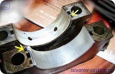
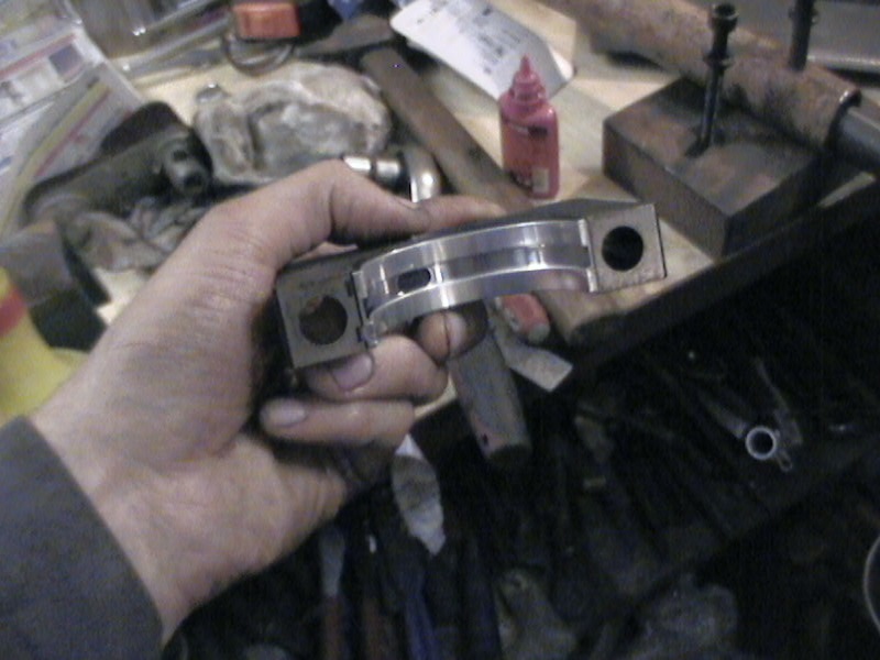
crankshaft liners - lock installation locations
You should also pay attention that there are recesses in the seats - the so-called locks (they are indicated by yellow arrows in the photo on the left). These recesses are used for laying the locks of the liners and allow you not to make mistakes during assembly and also prevent the liners from turning.
When installing, we lubricate all the crankshaft journals and new liners with new engine oil and install them in their places. Well, it remains to tighten all the bearing caps with the required torque, with the help of and you can install other engine parts in place (I already wrote about disassembling and assembling the engine, for example).
Well, the replacement of the liners can be clearly seen in the video below, using the example of a Ford Transit car.
I hope this article about crankshaft liners will be useful to novice drivers and repairmen, and if something is not clear to someone, then ask questions in the comments, good luck to everyone.
I still had to order other main and connecting rod bearings. Studied the Kolbenschmidt catalog. Those liners that I bought earlier are put on other engines (and ABT is not on their list). Well, we learn from our mistakes - you can’t blindly trust a site that gives out a spare part as an analogue according to the entered original number. We break through the proposed spare part only according to the manufacturer's catalog!
Of course, nothing terrible happened, but, you see, 2000 is also not lying on the road)
Correct main bearings for ABT engine - Kolbenschmidt 87 581 600 (VAG 026 198 491)
They still need stubborn half rings Kolbenschmidt 78 635 600 (VAG 026 198 421)
Indigenous liners
The previously purchased connecting rod bearings, as it turned out, also do not fit - not only are they without a hole for the piston pin lubrication channel, they are also 1 mm wider than those suitable from the Kolbenschmidt catalog. Also, they have a wider castle, respectively, they simply won’t even get into the connecting rod.
Correct connecting rod bearings for ABT engine - Kolbenschmidt 87 200 600 (VAG 026 198 501)
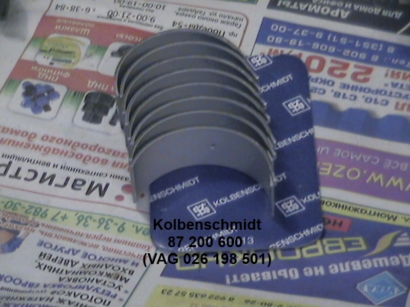
Connecting rod bearings for ABT engine
Once (before painting) the block was washed with Karcher and Profoam 1000, but then it stood for a long time, respectively, dust and dirt could fly there. I agreed with a friend who works in a car service, took the block and crankshaft to him. Everything was carefully blown out with compressed air - all channels, every hole. But before assembly, I additionally washed the oil channels in the block and crankshaft with white spirit under pressure from a syringe. Washed and sleeves.
Cleaned and degreased the bed
Degreased the bed
Installed inserts. smeared synthetic gear oil.
Bushings installed and lubricated
This is how persistent half rings are placed on the 3rd bed (the account is always kept from the timing belt)
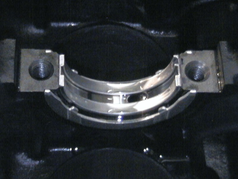
Thrust half rings
Installed the crankshaft. While twisting it is not worth it, because. thrust half rings will rotate with the crankshaft (they are fixed by the upper half rings)
Insert on the 4th yoke
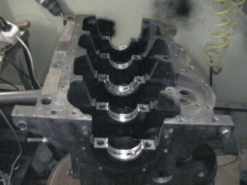
Lubed the inserts. Installed all the yoke (they are numbered). They are put lock to the lock of the bed. I lubricated the ends of the bolts and the surface on which the bolt head (on the yoke) rotates with oil.
The yokes do not immediately sit down in their places. Travnikov knocked them out with a copper ingot, but I screwed in the bolts and, trying to prevent the yoke from warping, carefully tightened first one, then the other.
The bolts on each yoke are tightened evenly, with a torque of 65 Nm. After tightening each yoke, check that the crankshaft rotates.
Yoke tightened
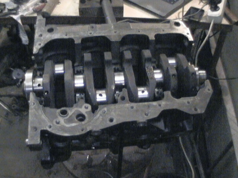
This is how the crankshaft rotates with tightened yokes
I bought new pistons (piston set Mahle 034 99 00), these are pistons for the ABK engine of the last years of production. The skirt is shortened, the piston pin is shorter. In addition, the ABK piston has a smaller recess on the bottom - a higher compression ratio. For gas, this is a plus.
Photo for comparison:
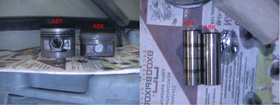
Pistons ABT and ABA
Piston installation.
First, I removed the old pistons from the connecting rods. Piston pin circlips are removed with a thin screwdriver. The finger is knocked out quite easily with a suitable mandrel, with a diameter slightly smaller than a finger (a bushing from some silent block from the 80s came up.
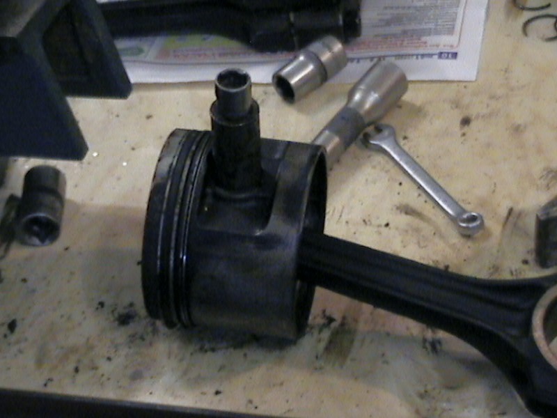
Washed the connecting rods, installed new pistons. The arrow on the bottom of the piston and the tides on the connecting rod must be on the same side. The lubricated piston pin is inserted into the piston and connecting rod by hand (this is precision workmanship!), The retaining rings are installed in place with a thin screwdriver.
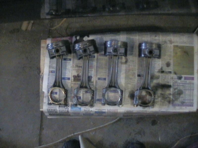
Connecting rods and pistons ready to install
Just like with root bearings, seats liners in the connecting rod are degreased, and the working surface of the liner itself is lubricated with oil. The locks of the rings are separated by 120º from each other, and the lock of the upper compression ring must lie in the plane of the crankshaft axis (according to the vag instructions)
Lubricate the sleeve with oil!
Using a tool, I inserted the pistons.
Related Articles