Synchronous alternators. principle of operation of synchronous generators
1. Stator. The stator of a synchronous generator, like other AC machines, consists of a core made of sheets of electrical steel, in the grooves of which an alternating current winding is laid, and a frame - a cast-iron or welded casing from sheet steel.
The stator winding is placed in the grooves stamped on the inner surface of the core. The insulation of the winding is carried out with particular care, since the machine usually has to work at high voltages. Micanite and micanite tape are used as insulation.
In FIG. 240 given the appearance of the stator of a synchronous generator.
2. Rotor. The rotors of synchronous machines are divided into two types by design:
A) explicitly pole (i.e., with pronounced poles) and
B) implicitly polar (i.e., with implicitly expressed poles).
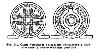
In FIG. 241 shows diagrams of the device of synchronous generators with salient and non-salient pole rotors.
One or another design of the rotor is dictated by considerations of mechanical strength. In modern generators rotating from high-speed engines (steam turbine), the circumferential speed of the rotor can reach 100-160 m / s (in some cases 170 m / s). Therefore, high-speed generators have a non-salient pole rotor. The speed of rotation of high-speed generators is 3000 rpm and 1500 rpm.
The salient pole rotor is a steel forging.
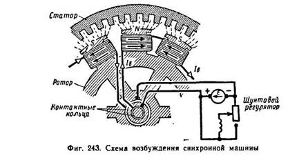
Poles are attached to the rotor rim, on which excitation coils are put on, connected in series with each other. The ends of the excitation winding are connected to two
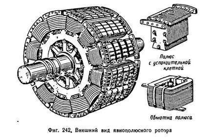
rings mounted on the rotor shaft. Brushes are superimposed on the rings, to which a constant voltage source is connected. In FIG. 242 shows the appearance of a salient pole rotor. Usually, a direct current generator, sitting on the same shaft with the rotor and called the exciter, gives a direct current to excite the rotor. The exciter power is 0.25-1% of the nominal power of the synchronous generator. Rated voltage of exciters 60-350 V.
In FIG. 243 shows the excitation circuit of a synchronous machine.
Self-excited synchronous generators are also available. A direct current to excite the rotor is obtained using selenium rectifiers connected to the generator stator winding. At the first moment, the weak field of residual magnetism of the rotating rotor induces an insignificant variable e in the stator winding. d.s. Selenium rectifiers connected to alternating voltage give a direct current, which strengthens the rotor field, and the generator voltage increases.
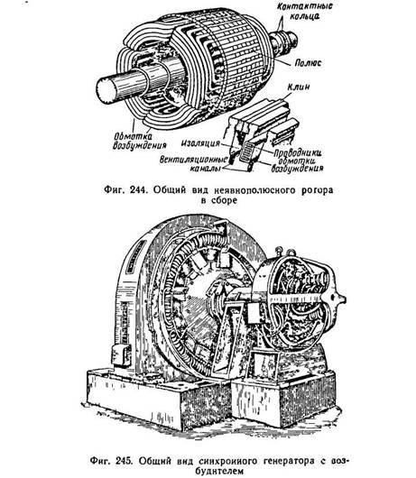
The non-salient pole rotor is made from a whole steel forging, subjected to complex thermal and mechanical processing. As an example, let us give the data of the rotor of a turbogenerator manufactured by the Elektrosila plant with a capacity of 100 thousand kW at n = 3000 rpm. Rotor diameter D = 0.99 m, length l=6.35 m. Circumferential speed of the rotor 155 m/sec. The machined rotor forging weighs 46.5 tons.
In the axial direction along the circumference of the rotor, grooves are milled, where the excitation winding is placed. The winding in the grooves is fixed with metal (steel or bronze) wedges. The frontal parts of the winding are fixed with shroud metal rings.
In FIG. 244 shown general form implicit-pole rotor of a turbogenerator in finished form.
When designing electrical machines and transformers, designers pay great attention to the ventilation of machines. For synchronous generators, air and hydrogen cooling is used.
Air cooling is carried out using fans mounted on a shaft on both sides of the rotor (for generators with a capacity of 1.5 to 50 thousand kW) or located under the machine in a foundation hole (for generators with a capacity of 100 thousand kW).
The masses of cold air entering for ventilation pass through filters to avoid contamination of the machine with dust. With a closed ventilation system, the machine is cooled by the same volume of air. The air, having passed through the machine, is heated and enters the air coolers, then is again forced into the machine, etc. For cooling purposes, the system of ventilation ducts arranged in separate parts of the machine also serves. The most efficient way to cool the machine is hydrogen cooling. Hydrogen, which has 7.4 times greater thermal conductivity than air, is better at removing heat from hot parts of the machine. Air-cooled friction losses are about 50°/o from
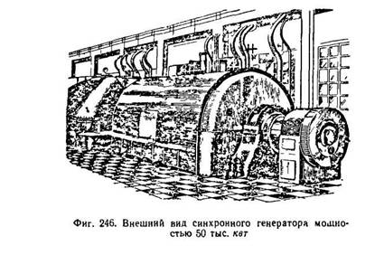
sum of all losses in the car. Hydrogen has a specific gravity 14.5 times less than air. Therefore, the friction against hydrogen decreases sharply. Hydrogen also contributes to the preservation of the insulation and varnish coatings of the machine. Appearance salient-pole synchronous generator with exciter is shown in Fig. 245, and a non-salient pole synchronous generator with a power of 50 thousand kW - in Fig. 246.
Hydrogenerators are driven by hydraulic turbines. These turbines most often have a vertical shaft with a low number of revolutions. The low-speed synchronous generator has a large number of poles and, as a result, large dimensions.
So, for example, a hydrogenerator of the type with a capacity of 50 thousand kW, manufactured by the Elektrosila plant named after. S. M. Kirov, has a total weight of 1142 g, a stator diameter of 14 m, a total height of 8.9 m, the number of poles is 96.
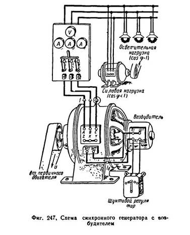
In FIG. 247 shows a diagram of a synchronous generator with an exciter supplying power and lighting loads. In FIG. 248 dan circuit diagram connections of the synchronous generator with the load.
The stator windings of synchronous generators are made in the same way as the stator windings of induction motors.
All six ends of the three-phase windings of the generator are usually displayed on its shield. By connecting the three ends of the windings into one common zero point and bringing the three beginnings of the windings into an external network, we get a star connection of the windings (Fig. 249, a). Connecting the end of the first winding with the beginning of the second, the end of the second with the beginning of the third, the end of the third with the beginning of the first winding and making three taps from the connection points to the external network, we get the connection of the windings in a triangle (Fig. 249, b).
In ship AC power plants, synchronous three-phase current generators with independent excitation and self-excitation are used. Generators with independent excitation have a mounted exciter (DC electric machine) with an automatic and manual voltage regulator. For self-excited generators, excitation is carried out through a semiconductor rectifier from the generator stator; voltage self-regulation is carried out by static devices.
Synchronous machines can operate as both generators and motors. Depending on the type of drive, synchronous generators have also received their names. A turbo generator, for example, is a generator driven by a steam turbine, a hydro generator rotates a water wheel, and a diesel generator is mechanically connected to an internal combustion engine.
Synchronous motors are widely used to drive powerful compressors, pumps, fans. Synchronous micromotors are used to drive the tape drive mechanisms of recording devices, tape recorders, etc.
The stator of a synchronous machine does not differ in design from the stator induction motor. Three-phase, two-phase or single-phase windings are placed in the stator slots. A noticeable difference is the rotor, which is fundamentally a permanent magnet or an electromagnet. This imposes special requirements on the geometric shape of the rotor. Any magnet has poles, the number of which can be two or more.
On fig. 7.1 shows two designs of generators, with a low-speed and high-speed rotor.
Fig.7.1
High-speed are, as a rule, turbogenerators. The number of pairs of magnetic poles they have is equal to one. For such a generator to produce electricity standard frequency f = 50 Hz, it must be rotated with a frequency
The principle of operation of a synchronous generator is based on the phenomenon of electromagnetic induction. A rotor with magnetic poles creates a rotating magnetic field, which, crossing the stator winding, induces an EMF in it. When connected to a load generator, the generator will provide AC power.
As shown above, the magnitude of the EMF induced in the stator winding is quantitatively related to the number of turns of the winding and the rate of change of the magnetic flux:
Turning to the effective values, the EMF expression can be written as:
where n is the generator rotor speed,
Ф - magnetic flux,
c is a constant factor.
When the load is connected, the voltage at the generator terminals changes to varying degrees. So, increasing the active load does not have a noticeable effect on the voltage. At the same time, inductive and capacitive loads affect the output voltage of the generator. In the first case, an increase in load demagnetizes the generator and reduces the voltage, in the second case, it is biased and the voltage rises. This phenomenon is called anchor reaction.
To ensure the stability of the generator output voltage, it is necessary to regulate the magnetic flux. When it is weakened, the machine must be magnetized, when it is increased, it must be demagnetized. This is done by regulating the current supplied to the excitation winding of the generator rotor.
The simplest three-phase current generator is similar in design to a three-phase current generator of a single-phase current, only its armature has not one, but three windings AX, BY, CZ, shifted in space relative to each other (Fig. 7.2). When the armature rotates in these windings, e. d.s. same frequency but different phases. If the amplitudes e. d.s. three windings of the generator are equal to each other, and the phase shift between any two adjacent e. d.s. equal to -j = 120 °, then the three-phase system e. d.s. called symmetrical.
Synchronous are called electrical machines, the rotational speed of which is connected by a constant ratio with the frequency of the alternating current network in which this machine is included. . Synchronous machines serve as alternating current generators in power stations, and synchronous motors are used in cases where a motor operating at a constant speed is needed. Synchronous machines are reversible, i.e., they can work both as generators and as motors. A synchronous machine switches from a generator mode to a motor mode depending on whether a rotating or braking mechanical force acts on it. In the first case, it receives mechanical energy on the shaft, and returns electrical energy to the network, and in the second case, it receives electrical energy from the network, and returns mechanical energy to the shaft.
A synchronous machine has two main parts: a rotor and a stator, and the stator does not differ from the stator of an asynchronous machine. The rotor of a synchronous machine is a system of rotating electromagnets that are powered by direct current supplied to the rotor through slip rings and brushes from an external source. In the stator windings, under the action of a rotating magnetic field, an EMF is induced, which is fed to the external circuit of the generator. The main magnetic flux of a synchronous generator, created by a rotating rotor, is excited by an external source - an exciter, which is usually a low-power DC generator, which is installed on a common shaft with a synchronous generator. Direct current from the exciter is fed to the rotor through brushes and slip rings mounted on the rotor shaft. The number of pairs of poles of the rotor is determined by the speed of its rotation. In a multi-pole synchronous machine, the rotor has p pairs of poles, and the currents in the stator winding also form p pairs of poles of a rotating magnetic field (as in an asynchronous machine). The rotor must rotate with the frequency of rotation of the field, therefore, its speed is equal to:
n=60f/p (9.1)
At f = 50Hz and p = 1 n = 3000 rpm.
Modern turbogenerators rotate with this frequency, consisting of a steam turbine and a high-power synchronous generator with a rotor that has one pair of poles.
In hydro generators, the primary engine is a hydraulic turbine, the speed of which is from 50 to 750 revolutions per minute. In this case, synchronous generators with a salient-pole rotor having from 4 to 60 pairs of poles are used.
The rotational speed of diesel generators connected to the primary engine - diesel, is in the range from 500 to 1500 rpm.
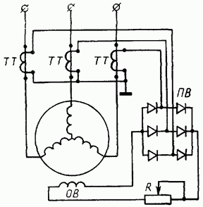
In low-power synchronous generators, self-excitation is usually used: the excitation winding is fed by the rectified current of the same generator (Fig. 9.2).
The excitation circuit is formed by CT current transformers included in the generator load circuit, a semiconductor rectifier assembled according to the three-phase bridge scheme, and the excitation winding OB with an adjusting rheostat R.
Self-excitation of the generator occurs as follows. At the moment of starting the generator, due to the residual induction in the magnetic system, weak EMF and currents appear in the working winding of the generator. This leads to the appearance of EMF in the secondary windings of CT transformers and a small current in the excitation circuit, which enhances the induction of the magnetic field of the machine. The generator emf increases until the machine's magnetic system is fully excited.
The average value of the EMF induced in each phase of the stator winding:
Еср = c∙n∙Φ (9.2)
n is the rotor speed;
Φ is the maximum magnetic flux excited in the synchronous machine;
c is a constant coefficient taking into account design features this machine.
Generator terminal voltage:
U = E - I z, where
I - current in the stator winding (load current);
Z is the impedance of the winding (one phase).
To fine-tune the amplitude of the EMF, the magnitude of the magnetic flux is regulated by changing the current in the excitation winding. The sinusoidality of the EMF is provided by giving a certain shape to the pole pieces of the rotor in salient-pole machines. In implicit-pole machines, the desired distribution of magnetic induction is achieved by special placement of the excitation windings on the surface of the rotor.
In synchronous machines, the magnetic field of the armature winding currents and the rotor rotate at the same speed (synchronously). Synchronous machines are reversible, that is, they can work as generators and as motors. However, they are most widely used as alternators, which are installed in all modern power plants.
The alternator was invented by the outstanding Russian electrical engineer P. N. Yablochkov. This generator was used to power electric candles and, according to the principle of operation, was no different from modern generators, being the first multi-phase generator. Several windings isolated from each other were laid on its stator, each of which had its own circuit with a group of candles.
In 1888, another outstanding Russian electrical engineer, M. O. Dolivo-Dobrovolsky, built the world's first three-phase generator with a power of about 3 kVA.
A synchronous generator has two main clocks, a rotor and a stator.
The rotor (moving, rotating part of the machine) forms a system of rotating electromagnets powered by direct current from an external source.
The stator (the fixed part of the machine) is no different from the stator of an asynchronous machine. In its winding, the action of the rotating magnetic field of the rotor induces an EMF supplied to the external circuit of the generator (in the engine mode, the mains voltage is applied to the stator winding). This design of the generator makes it possible to eliminate sliding contacts in the generator load circuit (the stator winding is directly connected to the load) and reliably isolate the working winding from the machine body, which is very important for modern generators manufactured for high power at high voltages. The main magnetic flux of a synchronous generator, created by a rotating rotor, is excited from an external exciter source, which is a conventional DC generator (with a power of 0.5-10% of the generator power). The exciter is mounted on a common shaft with the generator or connected to the generator shaft by a clutch or belt drive. The direct current from the exciter passes through the rotor winding through two rings and fixed brushes mounted on the rotor shaft.
According to their design, the rotors distinguish between salient pole (Fig. 5-25, a) and implicit pole (Fig. 5-25, b). The number of pairs of poles of the rotor is determined by the speed of its rotation. At a generated EMF frequency of 50 Hz, an implicit-pole rotor of a high-speed turbogenerator machine rotating at a speed
3000 rpm, has one pair of poles, while the salient-pole rotor of a low-speed hydro generator (the rotation speed of which is determined by the height of the water pressure), rotating at a speed of 50 to 750 rpm, has a number of pole pairs, respectively, from 60 to 4.
Low-power synchronous generators (up to 100 kVA), as a rule, are self-excited: the excitation winding is fed by the rectified current of the same generator (Fig. 5-26). The excitation circuit is formed by current transformers, included in the load circuit of the generator, a semiconductor rectifier PV, assembled, for example, according to a three-phase bridge circuit, and the excitation winding of the generator OB with an adjusting rheostat R.
Self-excitation of the generator occurs as follows. At the moment of starting the generator, due to the residual induction in the magnetic system, weak EMF and currents appear in the working winding of the generator. This leads to the appearance of EMF in the secondary windings of CT transformers and a small current in the excitation circuit, which enhances the induction of the magnetic field of the machine. The generator emf increases until the machine's magnetic system is fully excited.
Such generators (single-phase and three-phase) are used in low-power, low-voltage mobile power plants used, for example, in agriculture for electric shearing of sheep and milking cows, as well as for supplying rural mobile cinema installations, etc. In these generators, the working winding is often performed on a rotor, and on the inner surface of the stator, a pole system with pronounced poles is arranged. The generator is connected to an external load through sliding current collectors (brushes with rings on the rotor axis).
When the rotor rotates, the magnetic flux of the poles crosses the stator winding and induces an EMF in it according to the law of electromagnetic induction: E \u003d 4.44 * f * w * kw * F, where:
F is the frequency of alternating current, Hz; w is the number of turns; kw – winding factor; Ф - magnetic flux.
The frequency of the induced EMF (voltage, current) of the synchronous generator: f = p*n/60, where:
P is the number of pairs of poles; n is the speed of rotation of the rotor, rpm.
Replacing: E = 4.44*(n*r/60)*w*kw*F and, having determined: 4.44*(r/60)*w*kw - refers to the design of the machine and creates a design coefficient: C = 4.44* (p/60)*w*kw.
Then: E \u003d SE * p * F.
Thus, as with any generator based on the law of electromagnetic induction, the induced EMF is proportional to the magnetic flux of the machine and the speed of rotation of the rotor.
The principle of operation of a synchronous motor.
The principle of operation of a synchronous motor is based on the mutual influence of the magnetic fields of the armature and the poles of the inductor. With the inverted design of the unit, the location of the armature and the inductor is the opposite, that is, the first is located on the rotor, and the other on the stator. This option is used by cryogenic synchronous machines, in which the composition of the excitation windings includes materials with superconductivity properties.
When the engine is started, it is accelerated to a frequency close to that with which the magnetic field rotates in the gap. Only after that it goes into synchronous mode. In this situation, the magnetic fields of the armature and the inductor intersect. This moment is called the entry into synchronization.
Ways of excitation of synchronous machines.
To power the excitation winding, an exciter is provided, it is a DC generator, the armature of which is connected to the machine shaft, through the use of a mechanical device.
According to the method of excitation, synchronous machines are divided into two types:
Excitation of an independent type.
Self-excitation.
With independent excitation, the circuit implies the presence of a sub-exciter that feeds: winding of the main exciter, rheostat for adjustment, control devices, voltage regulators, etc. In addition to this method, excitation can be carried out from a generator that performs an auxiliary function, it is driven by a synchronous or asynchronous type motor.
For self-excitation, the winding is powered through a rectifier operating on semiconductors or ionic type.
For turbo and hydro generators, thyristor excitation devices are used. The excitation current is regulated automatically, using an excitation regulator, for low-power machines, the use of adjusting rheostats is typical, they are included in the excitation winding circuit.
Advantages and disadvantages of a synchronous motor.
A synchronous motor has several advantages over an asynchronous one:
1. High power factor cosФ=0.9.
The possibility of using synchronous motors in enterprises to increase the overall power factor.
3. High efficiency, it is more than that of an asynchronous motor by (0.5-3%), this is achieved by reducing losses in copper and large CosФ.
Possesses the big durability caused by the increased air gap.
The torque of a synchronous motor is directly proportional to the voltage to the first power. That is, the synchronous motor will be less sensitive to changes in the magnitude of the mains voltage.
Disadvantages of a synchronous motor:
The complexity of the starting equipment and the high cost.
Synchronous motors are used to drive machines and mechanisms that do not need to change the speed, as well as for mechanisms in which the speed remains constant with a change in load: (pumps, compressors, fans.)
Starting a synchronous motor.
In view of the absence of a starting torque in a synchronous motor, the following methods are used to start it:
Asynchronous motor start.
Start with auxiliary motor.
The start-up of a synchronous motor with the help of an auxiliary motor can only be carried out without a mechanical load on its shaft, i.e. practically idle. In this case, for the start-up period, the motor temporarily turns into a synchronous generator, the rotor of which is driven by a small auxiliary motor. The stator of this generator is connected in parallel to the network in compliance with all the necessary conditions for this connection. After the stator is connected to the network, the auxiliary drive motor mechanically switched off. This starting method is complex and has an auxiliary motor in addition.
Asynchronous motor start.
The most common way to start synchronous motors is asynchronous start, in which the synchronous motor turns into an asynchronous motor for the duration of the start. To enable the formation of an asynchronous starting torque, a starting short-circuited winding is placed in the grooves of the pole pieces of a salient-pole motor. This winding consists of brass rods inserted into the grooves of the tips and short-circuited at both ends with copper rings.
When the engine is started, the stator winding is connected to the AC network. The excitation winding (3) for the start-up period is closed to some resistance Rg, fig. 45, key K is in position 2, resistance Rg = (8-10) Rv. At the initial moment of starting at S = 1, due to the large number of turns of the excitation winding, the rotating magnetic field of the stator will induce an EMF Ev in the excitation winding, which can reach a very large value, and if the excitation winding is not turned on for resistance Rg during start-up, insulation breakdown will occur.
Rice. 45 Fig. 46.
The process of starting a synchronous motor is carried out in two stages. When the stator winding (1) is connected to the network, a rotating field is formed in the motor, which will induce an EMF in the short-circuited rotor winding (2). Under the action, which will flow in the rods current. As a result of the interaction of a rotating magnetic field with a current, a torque is created in a short-circuited winding, as in an asynchronous motor. Due to this moment, the rotor accelerates to slip close to zero (S=0.05), fig. 46. This ends the first stage.
In order for the motor rotor to be drawn into synchronism, it is necessary to create a magnetic field in it by turning on the DC excitation winding (3) (by switching the key K to position 1). Since the rotor is accelerated to a speed close to
to synchronous, then the relative speed of the stator and rotor fields is small. The poles will smoothly find each other. And after a series of slips, the opposite poles will be attracted, and the rotor will be drawn into synchronism. After that, the rotor will rotate at a synchronous speed, and its rotational speed will be constant, fig. 46. This ends the second stage of the launch.
28. Armature reaction of a synchronous generator with active, inductive, capacitive and mixed loads.
On fig. 20.5, and the stator and rotor of a two-pole generator are presented. The stator shows part of the phase winding. The rotor is salient pole, rotates counterclockwise. At the considered moment of time, the rotor occupies a vertical position, which corresponds to the maximum EMF E0 in the phase winding. Since the current under active load is in phase with the EMF, the indicated position of the rotor also corresponds to the maximum current. Having depicted the magnetic induction lines of the excitation field (rotor) and the magnetic induction lines of the stator winding field, we see that the stator MMF F1 is directed perpendicular to the excitation MMF Fv0. This conclusion is also confirmed by a vector diagram constructed for the same case. The procedure for constructing this diagram is as follows: in accordance with the spatial position of the generator rotor, we draw the excitation MMF vector Fv0; at an angle of 90 ° to this vector in the direction of lagging, we draw the vector of the EMF E0 induced by the magnetic field of excitation in the stator winding; when a purely active load is connected, the current in the stator winding I1 is in phase with the EMF E0, and therefore the MMF vector F1 created by this current is shifted in space relative to the vector Fv0 by 90 °.Rice. 20.5. The reaction of the armature of the synchronous generator with active (a),
Related Articles